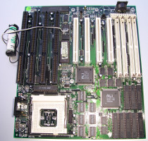
An American dealer offered this board on ebay with the hint: you can't find anything about it in the web. I thought: "Interesting board and if I drill a little bit deeper I will find the jumper settings / manual" and bought it.
But the statement of this dealer was absolutely correct. I looked through the "stason" database to find the board or, at least, a very similar one - no chance.
On vogons.org was later a discussion about this board where I also published my reverse-engineering results.
Jumper settings
Here is again a summary of all known jumper settings (includes the work of Robin4 from vogons.org):
| Jumper | Pins | Function | Comment | |
| JP9 | 1-2: 3-4: | open closed | 33MHz FSB | |
| 1-2: 3-4: | open open | 50MHz FSB | ||
| 1-2: 3-4: | closed open | 60MHz FSB | ||
| 1-2: 3-4: | closed closed | 66MHz FSB | ||
| JP23 | open closed | 1.5x 2.0x | CPU clock multiplier | A CPU with 133MHz core clock (2x 66MHz) is the fastest one for this board. |
| JP17 JP18 | 1-2: 1-2: | closed closed | Cache size 256kB | Only the 1MB version works for me and boots the OS from the hard disc. |
| 1-2: 2-3: | closed closed | Cache size 512kB | ||
| 2-3: 2-3: | closed closed | Cache size 1MB | ||
Some other jumpers are a little bit strange:
| Jumper | Comment |
| JP5 | Can connect socket 5 pin W33 with Pin 4 of the PCI-ISA bridge Ali M1449 but Intel and AMD say: pin W33 is not connected... |
| JP6 | Is on one side connected to pin S5 of the socket 5. According to the Intel datasheet this pin is used for debugging: "BreakPoint3". This pin is not connected in case of an AMD K5. |
| JP10 | Can set the pin 204 of Ali M1449 to 5V (default is 10k to ground). I haven't found a datasheet for this chip and I don't see any effects if the jumper is closed. |
| JP29 | The function of this jumper is unknown for me (one row is connected to ground). I found a similar construct in the manual of the Chicony CH1451A motherboard: "Green function connector" but in this case: the pins are outputs and not for jumpers. |
A new battery for the real time clock (RTC)
The Dallas/Maxim DS12887 module which was mounted on my board was empty - logically after so many years. You have two possibilities:
- The easiest one: Replace the DS12887 module which contains battery, crystal and chip by a new one. Disadvantage: if the battery is empty again in several years you will put all together into the electronic waste.
- You assemble all parts which are inside in the Dallas module yourself. You need: a Dallas DS12885 chip for U2, a 32.768kHz
crystal for X1 and a 3.6V lithium battery (I use an 1/2 AA size battery with wires).
Weak point: the battery pads on the motherboard aren't connected to pin 16 and 20 of U2. I connected the battery directly to the Dallas chip which looks a little bit unprofessional but it is good for the environment... :o)
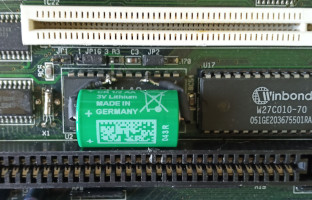
The layout of the board suggests two further possibilities:
- Use a CR2032 coin battery: you should stay away for this option because the layout of the board has a failure here: the positive pin of the battery holder is connected to ground.
- The classical 486 circuit with accumulator, MC146818 chip and external 32.768kHz clock. This was my first try but the BIOS doesn't save anything into the RAM of the MC146818. Perhaps, an other BIOS version is needed for this option...?
Power supply - CPU voltage regulator
The board ran for hours with an AMD K5 but NetBSD crashed shortly after starting the first benchmark. I realised the CPU voltage supply regulator (LT1085 from Linear Technology) was extremely hot... No wonder: the used voltage regulator can deliver a maximum current of 3.0A but an AMD K5 with 100MHz consumes up to 4.4A. Furthermore the mainboard manufacturer only spent a very small heat sink for the LT1085.
The board offers the possibility to place an additional LT1085 in parallel (but there is also only space for a very small heat sink).
I tested two options:
Two 5A linear regulators in parallel (LM1084IT-ADJ from National / Texas Instruments)
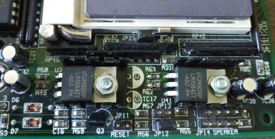
The head sinks are FK 231 SA 220 from Fischer Electronic. The exemplar for U41 needs a little bit special treatment with a round file:
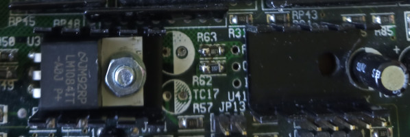
R50 and R63 have 120 Ohm. R49 and R62 have 220 Ohm in parallel with 22k (which should emulate a 217.9 Ohms resistor for 3.52V output voltage).
The disadvantage of this solution: two voltage regulators in parallel have slightly different output voltages which leads to transient currents.
I measured on U41 app. 52°C and on U33 42°C after 5 minutes bios screen.
Only one 5A linear regulator
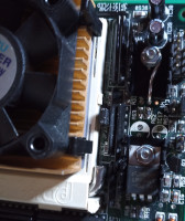
I removed U41 again but I kept its heat sink (a wire is needed from pin 2 - output of U41 - to the heat sink because the screw is electrical floating).
Now I measured 52°C on U33. I don't know if the additional heat sink really helps but I left it.
Much more important is: the air stream of the CPU fan should flow in direction of the heat sink. If I rotated the CPU fan 90 degree U33 became 10°C hotter.
I placed 100uF / 16V electrolytic capacitors (Panasonic, low ESR "FR" series) for TC21, TC27, TC31, TC32, TC38, TC39 to stabilize the linear regulator and the CPU supply.
IDE controllers for this boards
The motherboard doesn't contain any periphery chips (serial, parallel, floppy...). An PCI-IDE chip is needed to connect a hard disc (but not an IDE controller - the original bios of the motherboard can't boot a SCSI device or its emulation).
The most controllers which are tested below need the ISA interrupts 14 / 15 to work on this motherboard. These interrupts are fetched by a so called "paddle-board" which is put into the 16 bit part of an ISA slot (a paddle-board is shown on the photo of the Tekram controller).
A PCI0640B chip from CMD was quite common PCI-to-IDE bridge at this time:
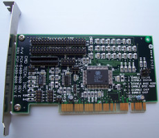
The CMD card is the only one which I get up and running with the native PCI-interrupt (without paddle-board) on this motherboard. The performance of this card is below a standard ISA-IDE controller (with PCI- and with ISA-interrupt)... Also the Linux kernel grumbles: "this is a buggy card..."
The OPTi and the National chips work quite good on this motherboard (with paddle-board, using the legacy ISA interrupt).
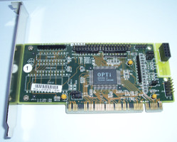
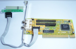
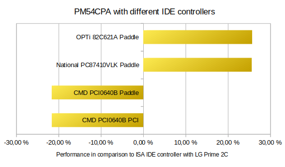
All measurement results can be found here.
New bios - new possibilities
Edwin van Boven from the cool webpage The Retro Web informs me: they found a new bios for this board.
Edwin, thank you very much for this hint because the bios from Unicore Software has a big benefit: you can boot from SCSI (or IDE) controller now... :o)
Facts
| Manufacturer: | Proect (???) |
| Year of manufacture: | February 1996 |
| Bios-String: | 04/10/96-ALI-1449/51/61-2A5KBP51C-00 |
| Bios: | Award (128kBytes) |
| Alternative Bios-String: | 09/22/1999-ALI-1449/51/6-2A5KBP51C-00 |
| Alternative Bios: | Award / Unicore (128kBytes) |
| Chipset: | ALI 1451 B1 (44/1995) ALI 1449 A3 (45/1994) |
| Manual: | Unknown |
falk.richter*at*yandex.com
Last update: September 18, 2023